NORDTEK DANMARK - AS Series Current Sensors - HF 20-200kHz - nordtek.se
AS Series Current Sensors - HF 20-200kHz
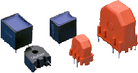
AS Series Current Sensors are designed as a low cost method of controlling, monitoring or measuring AC currents. The sensors serve as feedback elements between the output and pulse control circuitry providing accurate regulation of switch mode power supplies.AS-100 Series
AS-200/300 Series
AS-400 Series
Features
|
 |
Applications
Isolated current feedback signal in Switch Mode Power Supplies - Motor current load/overload - Lighting Switch Controls Ultra-sound current - High resolution sonar current - Isolated bi-directional current sensor with full wave bridge rectifier.AS-100 Series
Electrical Specifications at 25°C| Inductor Part Number | Prim/Sec Ratio | Lsec (1) (mH Min) |
DCRsec Ohms (Max) | Sec Term (2) Resistance Ohms (Nom.) | Isec (3) Max | Vols-µS (4) Max | Schematic |
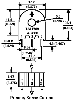
| AS-100 AS-101 AS-102 AS-103 AS-104 AS-105 |
1/50 1/100 1/200 1/300 1/500 1/750 |
6 25 100 250 700 1,682 |
0.6 1.1 4.5 10.0 25.0 43.0 |
50 100 200 300 500 750 |
300mA 150mA 75mA 50mA 30mA 40mA |
175 350 700 900 1,500 3,750 |
 |
| AS-110 AS-111 AS-112 AS-113 AS-114 AS-115 |
1/50CT 1/100CT 1/200CT 1/300CT 1/500CT 1/750CT |
6 25 100 250 700 1,682 |
0.3/0.3 0.55/0.55 2.25/2.25 5.0/5.0 12.5/12.5 21.5/21.5 |
25+25 50+50 100+100 150+150 250+250 375+375 |
300mA 150mA 75mA 50mA 30mA 40mA |
175 350 700 900 1,500 3,750 |
 |
| Notes: 1) Lsec: Secondary inductance tested at 10kHz and 10mV for 1:50 through 1:500. Prim./Sec. ratios and 1kHz/10mV for Prim./Sec. ratio of 1:750 2) This nominal termination resistance value will yield approximately 1.0V of output for each amp of current in a single turn sense line. The output Voltage/Ampere of these devices can be increased or decreased linearly over a restricted temperature range by adjusting the terminating resistance. 3) For Prim./Sec. Ratios of 1:50 through 1:500, the Isec value corresponds to a maximum primary current of 15 Amp-turns rms while the Isec values for the ratio of 1:750 corresponds to a max. primary current of 30 Amp-turns rms 4) VµS = Rt x ls x (1/2F) Rt (Ohms): Recommended Terminating Resistance Is (A): Secondary Current F (Hz): Frequency 5) Operating Temperature Range: -40°C to +120°C 6) Pin 2 is on Centre-Tapped (CT) versions only |
 |
#top#
AS-200/300 Series
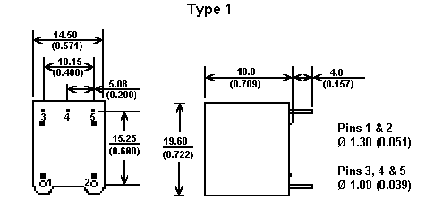
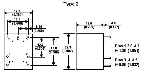
Electrical Specifications at 25°| Type 1 | Type 2 | Prim./Sec. Ratio |
Lsec (1) (mH Min.) |
DCRsec Ohms (Max) |
Sec. Term (2) Resistance Ohms (Nom.) |
Isec (3) Max. |
Volt-µS (4) Max. |
Schedule |
| AS-200 AS-201 AS-202 |
AS-300 AS-301 AS-302 |
1/50 1/100 1/200 |
5 20 80 |
0.65 1.30 4.50 |
50 100 200 |
300mA 150mA 75mA |
175 350 700 |
 |
| AS-210 AS-211 AS-212 |
AS-310 AS-311 AS-312 |
1/50 1/100 1/200 |
5 20 80 |
0.65 1.30 4.50 |
25+25 50+50 100+100 |
300mA 150mA 75mA |
175 350 700 |
 |
| AS-320 AS-321 AS-322 |
1/50 1/100 1/200 |
5 20 80 |
0.65 1.30 4.50 |
50 100 200 |
300mA 150mA 75mA |
175 350 700 |
 |
|
| AS-330 AS-331 AS-332 |
1/50CT 1/100CT 1/200CT |
5 20 80 |
0.65 1.30 4.50 |
25+25 50+50 100+100 |
300mA 150mA 75mA |
175 350 700 |
 |
#top#
AS-400 Series
Features:
- Meets requirements of IEC 950 and VDE norms
- UL 94-V0 recognized materials
- Operating frequency range from 20 kHz to 200 kHz
- Operating Temperature Range: -40 °C to +120 °C
- Primary to secondary isolated to 4000 VAC
- Primary current rating to 80 Amps
Electrical Specifications at 25°C
| Part Number |
Prim./Sec Ratio |
Ip A | Volt-µS (4) Max. |
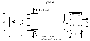
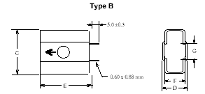
Application | Schedule | Box Type | Dimensions | |||||||
| C | D | E | F | G | H | I | Hole | |||||||
| AS-400 AS-401 AS-402 |
1/100 1/100 1/100 |
1 2 5 |
350 550 1,500 |
Switching Switching Switching |
 |
A A B |
17.8 23.0 32.5 |
12.8 15.5 18.0 |
20.0 25.0 35.5 |
10.0 12.5 15.0 |
5.0 10.0 12.5 |
15.0 20.0 - |
5.0 5.0 - |
- - - |
| AS-403 | 1/100 | 10 | 1,500 | Switching |  |
A | 32.5 | 18.0 | 35.5 | 15.0 | 12.5 | - | - | - |
| AS-404 AS-405 AS-406 AS-407 |
1/100 1/500 1/500 1/500 |
50 50 65 80 |
1,500 2,700 4,200 7.500 |
Switching Switching Switching Switching |
 |
B A A B |
32.5 23.0 27.0 32.5 |
18.0 15.5 18.0 18.0 |
35.5 25.0 30.0 35.5 |
15.0 12.5 15.0 15.0 |
12.5 10.0 12.5 12.5 |
- 20.0 22.5 - |
- 5.0 5.0 - |
Ø 8 Ø 6 Ø 8 Ø 8 |
 |
 |
#top#
Nordtek Denmark - current sensor, ei30, ee20, pcb transformer, vergossen, plug in transformer, topswitch, simple switcher
Nordtek Com - transformer design, magnetics, impedance, transformer ac, toroids
strommessung, netztrafo, power supply,voltage transformer, telecom transformer, pulse
current sense transformer, drossel, current sense transformer, inductive, ferrite, kleintransformatoren
inductor, inductance, 3c85, 3f3, power transformer, toroid, 50/60hz, line transformer, emi
electronic starter, flicker starter, fluorescent lamps, safety starter, lamp starter, glow starters, tubestarter, rapid, ts8, sunbed, halogen transformer

