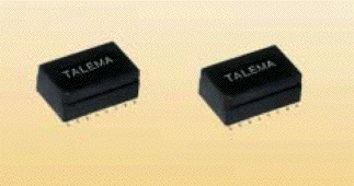
U Port SMD 2xInterface 1,5KV

Features
|
 |
|
| Electrical Specifications @ 25°C | Turns Ratio: Bold = IC Side Windings | |
Surface Mount UPO Interface Transformer Modules
Complies with Basic Insulation level EN60950, UL1950 and UL1459| Part Number | Turns Ratio ±2% |
LP (mH Min.) |
^IDC (mA) |
LL (µH) |
CC (pF Max.) |
DCR (Ohms per winding) | VP (Vrms) |
Schematic | |
| Pri | Sec | ||||||||
| UAJ-140C | 1:1:2:2 | 1.7 | 75 | 5 | 150 | 0.8 | 1.6 | 1,500 | C |
| Test Conditions: | ||
| Inductance: | Line side windings in series - measurement @ 10kHz, 100mVrms | |
| Leakage Inductance: | Line side windings in series, IC side windings short circuited - measurement @ 100kHz, 100mVrms | |
| Coupling Capacitance: | IC side winding (windings in series) to Line side windings in series @ 10kHz, 100mVrms | |
| Test Voltage: | 1.5kV for 2 sec. - w1 w2 to w3 w4 0.5kV for 2 sec. - w1 w3 to w2 w4 |
|
| High Voltage Test: | UPULSE(w1 w2 to w3 w4); 2kVOPfor 10µS/700µS wave form, 10 pulses in 10 second cycle with changing polarity |
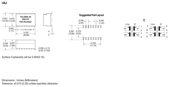
Dimensions & Schematic

Features
|
 |
|
| Electrical Specifications @ 25°C | Turns Ratio: Bold = IC Side Windings | |
Surface Mount UPO Interface Transformer Modules
Complies with Basic Insulation level EN60950, Ul1950 and Ul1459| Part Number | Turns Ratio ±2% |
LP (mH Min) |
^IDC (mA) |
LL (µH) |
CC (pF Max.) |
DCR (Ohms per winding) | VP (Vrms) |
Schematic | Double Choke | ||
| Pri | Sec | LN (mH) |
DCR (Ohms) |
||||||||
| UAJ-120A-502 UAJ-130A-502 UAJ-140B-502 |
1:1:2 1:1:2,5 1:1:2:2 |
1.7 1.7 1.7 |
75 75 75 |
5 5 5 |
100 100 180 |
0.8 0.5 0.8 |
1.6 1.0 1.6 |
1,500 1,500 1,500 |
A A B |
5 5 5 |
0.4 0.4 0.4 |
| Test Conditions: | ||
| Inductance: | Line side windings in series - measurement @ 10kHz, 100mVrms | |
| Leakage Inductance: | Line side windings in series, IC side windings short circuited - measurement @ 100kHz, 100mVrms | |
| Coupling Capacitance: | IC side winding (windings in series) to Line side windings in series @ 10kHz, 100mVrms | |
| Test Voltage: | 1.5kV for 2 Sec. - Line side windings in series to IC side winding (IC windings in series) | |
| Inductance CM Choke: | Measured @ 10kHz, 100mVrms |
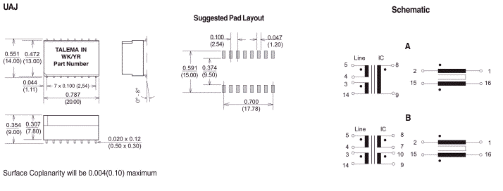
Dimensions & Schematic

Dimensions: Inches (Millimeters)
Tolerance: ±0.010 (0.25) unless specified otherwise
Nordtek Denmark - current sensor, ei30, ee20, pcb transformer, vergossen, plug in transformer, topswitch, simple switcher
Nordtek Com - transformer design, magnetics, impedance, transformer ac, toroids
strommessung, netztrafo, power supply,voltage transformer, telecom transformer, pulse
current sense transformer, drossel, current sense transformer, inductive, ferrite, kleintransformatoren
inductor, inductance, 3c85, 3f3, power transformer, toroid, 50/60hz, line transformer, emi
electronic starter, flicker starter, fluorescent lamps, safety starter, lamp starter, glow starters, tubestarter, rapid, ts8, sunbed, halogen transformer


