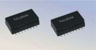
MHJ -3kV Interface Transformer Modules

Features
Standard Packaging: Tape and Reel |
 |
|
| Electrical Specifications @ 25°C | Turns Ratio: Bold = IC side windings |
3kV Modules comply with Reinforced Insulation Level EN60950
| Part Number | LP (mH Min.) |
Turns Ratio ±1% |
LL (µH Max.) |
^IDC (mA) |
CC (pF Max.) |
RCUP (Ohms) |
RCUS (Ohms) |
VP (Vrms) |
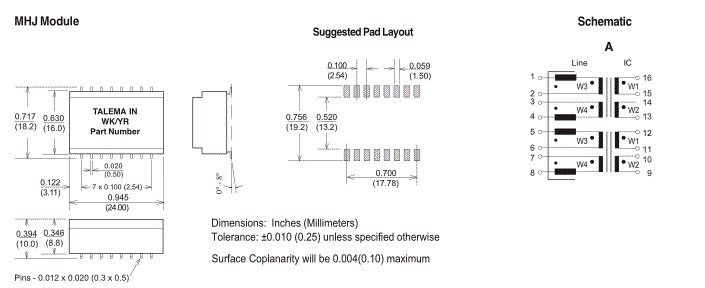
Schematic |
| MHJ-200B1-XXX MHJ-240B1-XXX MHJ-230B1-XXX |
30 30 30 |
1:1:1:1 1:1:2:2 1:1:2.5:2.5 |
10 10 10 |
4 4 4 |
75 75 75 |
1.7 1.7 1.7 |
1.9 3.7 4.4 |
3,000 3,000 3,000 |
A A A |
|
Test Conditions: So Transformer modules comply with Reinforced Insulation Level EN60950:1992/A4: 1997, para. 2.9.4.4 when tested in accordance with 6.4.1
|
|||||||||||||||||||||||||

Nordtek Denmark - current sensor, ei30, ee20, pcb transformer, vergossen, plug in transformer, topswitch, simple switcher
Nordtek Com - transformer design, magnetics, impedance, transformer ac, toroids
strommessung, netztrafo, power supply,voltage transformer, telecom transformer, pulse
current sense transformer, drossel, current sense transformer, inductive, ferrite, kleintransformatoren
inductor, inductance, 3c85, 3f3, power transformer, toroid, 50/60hz, line transformer, emi
electronic starter, flicker starter, fluorescent lamps, safety starter, lamp starter, glow starters, tubestarter, rapid, ts8, sunbed, halogen transformer


